Step 1: Build a load inventory
List each load with its kW (or hp), power factor, starting method and whether it must run on generator. Separate life-safety (NEC Article 700), legally required standby (701) and optional standby (702) loads, which have different rules.
Step 2: Running load
Sum running kW and kVA. Motors: kW ≈ hp × 0.746 ÷ efficiency. Generators are typically rated at 0.8 PF, so kVA rating = kW rating ÷ 0.8.
| Load | Running kW | Starting |
|---|---|---|
| Lighting & receptacles | 40 | — |
| 2 × 25 hp pumps (VFD) | 2 × 20 = 40 | Soft (VFD) |
| 50 hp chiller compressor | ~42 | Across-the-line |
| IT/UPS load | 30 | Non-linear |
| Total running | ~152 kW |
Step 3: Motor starting
Starting kVA for an across-the-line motor can be estimated from its NEMA code letter (kVA/hp at locked rotor). A code G 50 hp motor draws roughly 300 kVA briefly. Generators are selected so the largest step load keeps voltage dip within limits (often 15–35%, depending on loads). Sequencing loads, soft starters or VFDs can cut the required size substantially.
Step 4: Non-linear and regenerative loads
UPS systems, VFDs and LED drivers distort current waveforms and can affect voltage regulation. Manufacturers often recommend oversizing the alternator or using a permanent-magnet exciter. Check with the generator supplier's sizing software.
Step 5: Derating and site conditions
- Altitude and ambient temperature derating per manufacturer data
- Fuel type: diesel, natural gas or bi-fuel. Gas units often have weaker load-step response.
- Emissions (EPA tier) and local permitting
- Enclosure sound level and placement setbacks
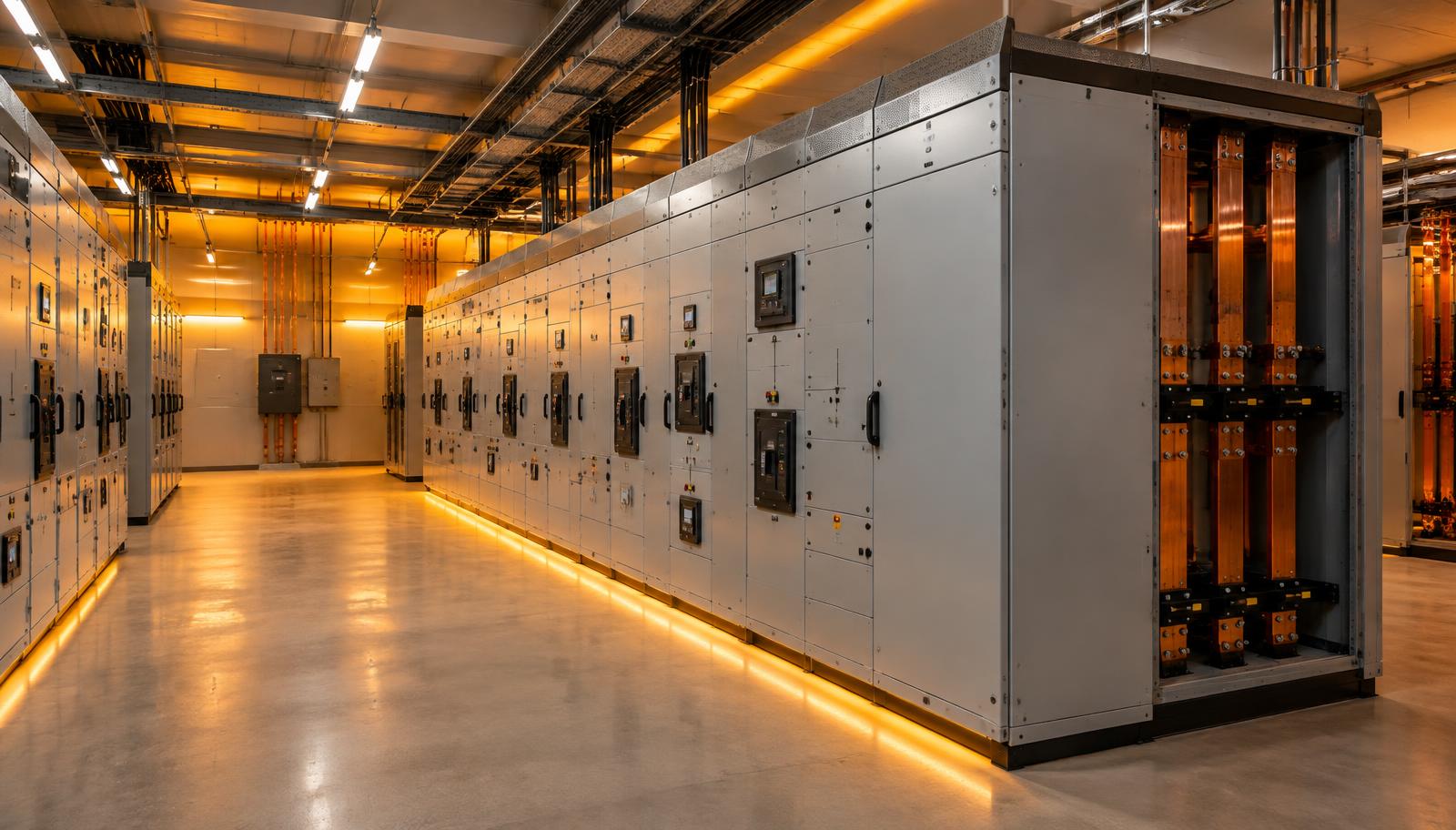
Step 6: Transfer switch and integration
Choose an ATS with matching voltage and amperage, the right number of poles (3- or 4-pole for neutral switching), and a withstand rating suited to available fault current. Plan grounding carefully, because a switched neutral changes whether the generator is a separately derived system. Related: Industrial Solutions.