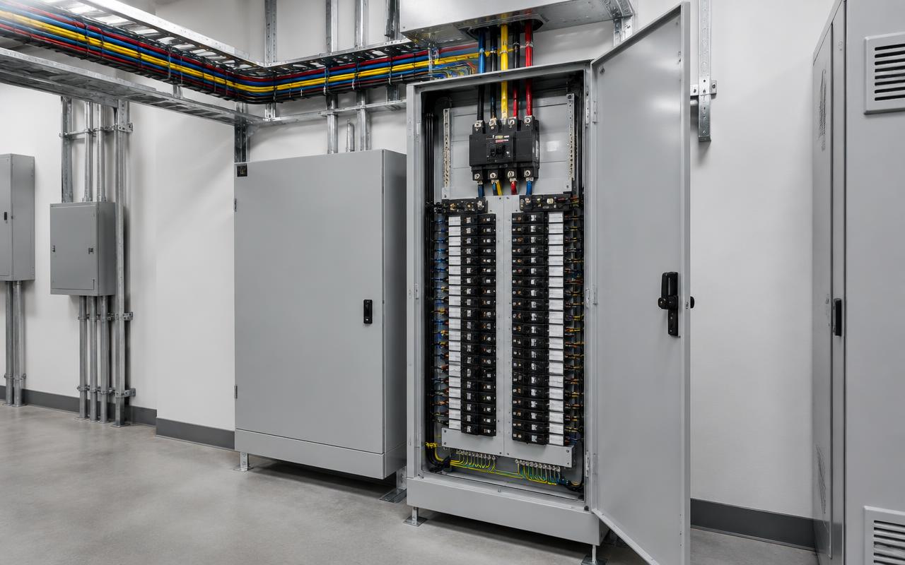
Phase identification
The NEC requires ungrounded conductors to be identified by phase and system at panels (210.5(C), 215.12(C)), with the method posted. Common US industry conventions:
| System | Phase A | Phase B | Phase C | Neutral |
|---|---|---|---|---|
| 208Y/120 V | Black | Red | Blue | White |
| 480Y/277 V | Brown | Orange | Yellow | Gray |
These are conventions, not universal mandates; follow the site's posted scheme. On high-leg delta systems, the high leg must be marked orange (NEC 110.15).
Conductor sizing and voltage drop
- Size for ampacity from NEC 310.16 with temperature and bundling adjustments, and 125% for continuous loads.
- Termination temperature ratings (often 75 °C) can limit usable ampacity.
- NEC informational notes suggest a maximum of 3% voltage drop on feeders and 5% overall. Long runs often need upsizing.
- Three-phase voltage drop ≈ √3 × I × L × (R cos θ + X sin θ), with L as one-way length.
Neutrals and harmonics
In a 4-wire wye system, balanced linear loads cancel in the neutral. Triplen harmonics from computers, LED drivers and VFDs add in the neutral instead. Where those loads dominate, the NEC counts the neutral as a current-carrying conductor (310.15(E)), and designers often specify oversized or dedicated neutrals.
Load balancing
Spread single-phase loads evenly across A, B and C. Even a small voltage unbalance causes a much larger current unbalance in motors and adds heating. NEMA MG 1 calls for derating above 1% voltage unbalance. Diagnostics: Common Problems.
Grounding, bonding and workmanship
- Run an equipment grounding conductor with every circuit, sized per NEC 250.122.
- Torque terminations to the manufacturer's values, documented per NEC 110.14(D).
- Keep working clearances (NEC 110.26) and label panels and disconnects.
- More detail: Grounding Three-Phase Systems and the Safety Handbook.